RadioMapper Package
Version 1.2
MAXSCRIPT ENCRYPTED / CONVERTIBLE DEMO (9/30/1998)
Copyright (c) 1998 by Borislav Petrov, Bobo's Rendert**ls.
http://gfxcentral.com/bobo/
Distributed exclusively by ANIMAPIX GmbH
HELP TOPICS
1.Short Description
2.The RadioMapper Package
2.1.RadioMapper
Package Overview
2.2.Registering
Radiomapper
3.Step-by-step Workflow
3.1.Creating
and Importing the Radiosity Mesh
3.2.TexPlode
- Simplifying Radiosity Meshes
3.2.1.TexPlode
Overview
3.2.2.TexPloding
Simple Meshes with Planar Segments
3.2.3.TexPloding
Cylinders
3.2.4.TexPloding
Meshes with Partially Curved Segments
3.3.Using
RadioMapper
3.4.1.RadioMapper
Overview
3.4.2.Starting
the RadioMapper Utility
3.4.3.Setting
Bitmap and Material Properties
3.4.4.Setting
UVW Coordinates
3.4.5.Creating
RadioMapper Bitmaps
3.4.6.Using
the Batch Mode
1. SHORT DESCRIPTION
-
The RadioMapper Package includes tools for converting
Radiosity
Solution data in 3D Studio MAX 2 and higher
into Bitmaps
(also known as Lightmaps).
-
RadioMapper works in conjunction with Kinetix RadioRay(tm)
Radiosity Renderer based on the Lightworks Radiosity technology, but can
be used also with any other VRML source files providing ColorPerVertex
information.
-
RadioMapper uses radiosity meshes imported using the
VRML
Importer of MAX 2.5 or the WorldGrabber(tm) VRML Importer Script
0.4x or higher.
-
It lets you use VERY LOW polygon count models with texture
map representation of the radiosity solution instead of VERY COMPLEX meshes
with VertexColor shading.
-
RadioMapper can be useful for fast real-time graphics
in simulations, games, VRML worlds etc.
-
The current package includes the RadioMapper utility
itself, along with the TexPlode mesh-splitting utility, this help file
and a sample mesh file.
2. THE RADIOMAPPER
PACKAGE
2.1. RADIOMAPPER PACKAGE OVERVIEW
Version 1.2 (9/30/98) Convertible Demo
-
This version of the RadioMapper utility will work in
Demo
Mode until registered.
-
In Demo Mode, a red cross will be drawn over the radiosity
texture.
-
To register, please contact ANIMAPIX GmbH
and send the Serial Number displayed in the Registration
rollout.
-
You will receive a Registration Number based
on your MAX hardware lock which will register the utility and remove the
Demo Mode limitations.
-
The package also includes a free version of the
TexPlode utility to help you split complex Radiosity Meshes into
simpler geometry.
2.2. REGISTERING
RADIOMAPPER
-
Start the RadioMapper Utility
- go to Utility/MAXScript/Run Script, select the RadioMapper MSE
file
-
Select the RadioMapper from the Drop-down list -
the rollouts will open.
-
If you are starting RadioMapper for the first time,
the MAXScript Listener will report the following:
Initializing RadioMapper...
No INI file found. Using Defaults.
RadioMapper NOT REGISTERED.
Switching to DEMO MODE.
MAX R2.5 or higher detected.
-
In the Title rollout, the last line will read "DEMO
MODE"
-
Go to the last rollout - "Register RadioMapper"
-
The S/N: xxxxxxxx will report the Serial Number calculated
using your MAX's hardware lock serial number.
-
Please contact ANIMAPIX GmbH and send this Serial Number
along with your name and email address.
-
You will receive a Registration Number based on the
Serial Number and your hardware lock.
-
Enter the Registration Number in the REG.# field
-
Press the [Register!] button
-
A message will appear "RadioMapper was sucessfully registered"
-
There will be a new text "REGISTERED" in the Title rollout.
-
The registration information is saved in the file "RMSERIAL.INI"
in the root directory of the C: disk.
-
In case this file is deleted, corrupted, or the disk
has changed, you will have to reenter the Registration Number.
-
The Registration Number will work only with your
copy of 3D Studio MAX.
3. STEP-BY-STEP
WORKFLOW
3.1. CREATING AND IMPORTING
THE RADIOSITY MESH
-
Set up your MAX scene for Radiosity as described in
the RadioRay manuals.
-
Process the scene with the Radiosity Processor in the
Utility tab.
-
Export the resulting solution as Radiosity VRML file
(.WRL) using the "File/Export... Radiosity VRML" option of MAX.
WARNING: In the current
release of RadioRay (1.1), you cannot export a radiosity solution VRML
file from a previously saved MAX scene.
You should do this immediately
after processing the scene and before leaving MAX.
-
Reset your MAX scene (MAX 2.5 VRML Importer will do
this for you if you leave the respective checkbox checked)
-
Import the Radiosity VRML (.WRL) file using the VRML
Importer built in MAX 2.5, or using the free WorldGrabber script in MAX
2
NOTE: WorldGrabber is
a Beta version of a free script and is not part of the RadioMapper Package.
-
If you are using the MAX 2.5 VRML Importer, uncheck
the "Turn to 3DS Coordinates" checkbox.
-
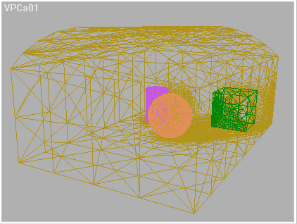
The imported file consists of very complex Editable
Meshes representing the radosity solution calculated by RadioRay.
-
The color information is saved in every vertex of the
EMesh as "Color-Per-Vertex" (CPV) information.
NOTE: 3DS MAX R2 and
higher use the second UVW map channel for the CPV information, so you can
use just UVW Channel 1 on such meshes.
-
After importing, the object property "Vertex Colors"
is turned on.
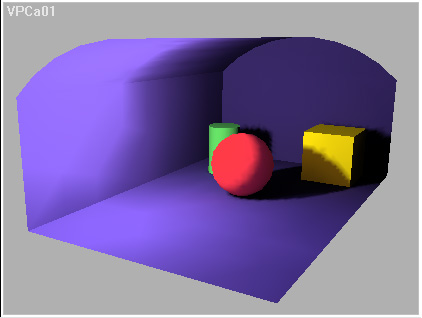
-
In a shaded viewport, the colors are interpolated using
Gouraud shading and you can see the Radiosity solution in realtime.
-
The objects will have default names because the Radiosity
VRML Exporter does not save any names.
-
In the scene, you might also find a Camera node and
(in case of MAX 2.5 VRML Importer), some seperator helpers without geometry
which can be deleted.
-
Press C to switch to the Camera view.
-
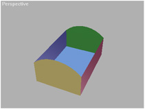
The imported mesh looks like this:
WARNING: The MAX
2.5 VRML Importer will set the Clipping Planes of the Camera to "Manual,
0/999999", which will cause errors in the shaded OpenGL display of MAX.
You should set the Clipping to Automatic to get correct display.
Also, the Environment.../Ambient Light value will be set to a too high
value you might wish to correct.
RadioMapper is capable of mapping relatively simple
face structures like almost coplanar, cylindrical and spherical sets of
faces. You should reduce complexity of some meshes before you can use RadioMapper
with them. The next chapter describes the basics of the TexPlode Utility,
and some manual methods for editing Radiosity Meshes.
3.2.
TEXPLODE - SIMPLIFYING RADIOSITY MESHES
-
The TexPlode utility does the same as the EditMesh /
Explode and Detach functions.
-
Other than EditMesh, it does not destroy the
CPV information of the source mesh.
WARNING: When trying
to split a Radiosity Mesh with EditMesh, the selected faces that become
a new object receive the correct Vertex Color information. The rest of
the mesh will have corrupted CPV information!
TIP: Sometimes you might
find it easier to use the EditMesh Modifier or EMesh node functions instead
of TexPlode.
To split a single mesh
into two parts with correct CPV information, do the following:
-
Select the Mesh
-
Press the SHIFT key and click
on the Mesh with the Move tool.
-
Create a Copy of the Mesh.
-
Go to Sub-Oobject/Faces in
the one copy, select the faces to detach
-
Press the Detach button.
-
Enter the name prefix for the
new object.
-
Uncheck the Sub-Object button,
press the DEL key to delete the Mesh.
-
Select the second mesh, and
repeat the same steps, but select the other part to detach.
-
Both detached faces will keep
their correct CPV info.
-
The TexPlode utility scans all face normals in the Mesh
and groups them based on an Normal Threshold value.
-
Then, it detaches the faces with normals falling in
the same group to separate objects.
-
The process is automatic, but might take minutes and
even hours with very complex meshes (100.000 faces and more).
TIP: To avoid long
processing times, there are some things you should keep in mind while creating
your scene for Radiosity processing:
-
RadioRay divides shadow zones
and areas with quickly changing light conditions (Shadow/Light) finer than
bright regions. To reduce the complexity of the mesh, you might want to
detach faces that are in areas not included in the Radiosity solution (like
the outside walls of a room illuminated by a Liminaire light source inside)
BEFORE processing the scene.
-
TexPlode lets you detach just
a selection of faces - the utility effectively skips any faces not in the
selection. In the case of a single Mesh with 200.000 faces, of wich
150.000 are on absolutely dark faces out of reach of any light sources
or invisible to the camera, TexPlode will have to deal with just 50.000
selected faces.
3.2.1.
TexPlode Overview
-
The TexPlode Utility has 2 rollouts
-
In the "About..." group, you can see the current version
of the utility, and the author's homepage address.
-
The [Close] button will close the Utility.
-
Use the MAXScript Drop-down list to start again if you
close it for some reason.
-
The "TexPlode Controls" rollout contains all settings
required to work with the Utility
-
The "Source Mesh" group lets you select a mesh, set
a face selection, and start the splitting process.
-
The [Select EMesh] pickbutton is used to select
the EMesh to work with
-
You can click on a Mesh in the viewports, or hit the
H key to select by name
-
The text in the button will change to [EMesh: Nodename]
to indicate the mesh you selected.
-
The [Set Selection] button is activated after
a correct EMesh has been selected. It brings you in EditMesh/Sub-object/Face
mode and lets you select faces to work with.
-
The [TEXPLODE MESH] button is activated after
a correct EMesh has been selected. It starts the TexPloding process.
-
It will read [TEXPLODE SELECTION] when the [Use
EMesh Selection] is checked.
-
When the [Use EMesh Selection] is checked, a
Sub-object/Face selection is used instead of the whole mesh. It will be
checked automatically after using the [Set Selection] function.
-
The [Combine Selection] checkbutton forces TexPlode
to ignore the Normal settings and connect all selected faces to a single
mesh. It is unchecked by default.
-
The [Delete Old Mesh] checkbutton is checked
by default. It will be unchecked after using the [Set Selection] function.
When it is checked, the original mesh
-
is deleted after the the TexPlode meshes are created.
It can be Undone separately using the MAX Undo function after TexPloding.
-
The [Create New Meshes] checkbutton is checked
by default and should be left as is. It can be unchecked in case you just
want to test what Normals will be detected by TexPlode.
-
The [Hide New Meshes] checkbutton is unchecked
by default. You can check it if you want the newly created meshes to be
hidden after creation.
-
The "Mesh Options" group defines the Mesh creation settings.
-
The "Prefix" field reads "TexPlode" by default and is
used as a name prefix for the newly created meshes. You should change it
before using TexPlode, sincle it will be also used by RadioMapper as bitname
name.
-
The "Normal Threshold" value is the angle value used
to separate the normals encountered.
-
The "Linear Threshold" shows the linear deviation in
the normal vercor's coordinates corresponding to the "Normal Threshold"
angle.
INFO: Here is how the Normal
Threshold is used:
-
TexPlode takes the first face
normal encountered
-
It compares every other normal
with the first normal
-
If the angle between the two
normals is higher than the "Normal Threshold", the second normal is taken
into the list of unique normals.
-
The next vectors are compared
with all unique normals in the list encountered so far....
-
The "MaxScript Memory" group provides information and
control over the MAXScript Memory Heap.
-
The "Memory Heap" reports the current memory settings.
-
The [Increase by 1MB] button lets you increase
the total MAXScript memory.
INFO: The MAXScript Memory
Heap
-
MAXScript uses by default only
5,5MB of the system memory.
-
Tests with TexPlode showed
that this amount is often not enough when working with large meshes.
-
TexPlode will increase this
amount to 15,5MB when first started.
-
The only way to reduce the
MAXScript Memory Heap is to restart MAX.
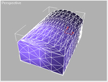
3.2.2.
TexPloding Simple Meshes with Planar Segments
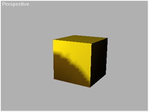
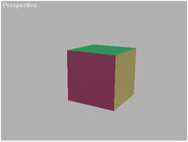
In the case of a Box or similar regular meshes like
flat walls, floors, ceilings etc., you have to do the following:
-
Start TexPlode: Go to MAX Utility Tab, open MAXScript,
press "Run Script" and select the Texplode file from the menu. Then pick
the TexPlode from the scripts drop-down list.
-
Press the first button labeled [Select EMesh] - it will
turn green. You can now click on the object to texplode, or press the H
button to select by name. The Object must be an Editmable Mesh to be texploded,
but MUST NOT have CPV information.
-
The [TEXPLDOE MESH] button will become available,
and the name of the node will be displayed on the "Select EMesh" button.
-
Enter the desired Name Prefix in the "Mesh Options"
group. Leave all other options to their default settings.
-
Press the [TEXPLODE MESH] button.
-
The MAXScript Listener window is used to display information
about the process. In MAX 2-5, it will open automatically. In MAX 2.0,
you will have to make sure it is open before you start texploding.
-
TexPlode will report the found Unique Face Normal vectors.
-
After scanning the whole mesh, the number of unique
Normals found will be reported, and new meshes will be created based upon
this information.
-
The new meshes will receive CPV information if available,
but their "Vertex Colors" properties will NOT be activated so you can distinguish
them from any imported or already RadioMapped objects. (See Image)
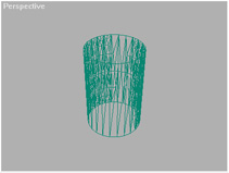
3.2.3.
TexPloding Cylinders
There are two ways to texplode a Cylinder:
Using the Normal Threshold value:
-
Select the Cylinder mesh.
-
Enter 45,0 in the Normal Threshold filed.
-
Start TexPloder
-
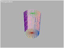
The Cylinder will be split into 8 parts, 2 of them will
be the Capping faces, and 6 the side segments.
-
Select one of the Side Segments, go to Modify, press
Attach and click the other 5 segments.
-
You have 3 parts now - one cylindrical and two planar.
-
Apply a Cylindrical UVW Map to the cylindrical part
for later RadioMapper usage.
TIP: The Attach function
DOES NOT destroy any CPV information and may be used anytime you get parts
from TexPlode you want to put together - this can save you some texture
maps later in RadioMapper... You can also Weld the vertices of the attached
elements without destroying CPV data. This way, you can actually build
back the original mesh out of the texploded parts anytime.
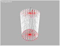
Using the Face Selection option:
-
Select the Cylinder Mesh
-
Press the Set Selection button - you will be taken to
EditMesh Sub-Object/Face Mode
-
Right-click the Viewport name and go to Wireframe Mode.
-
Make sure the "Ignore Visible Edges" checkbox is checked
-
Select the Top Capping of the Cylinder - it turns red
-
Rotate the Perspective View to see the Bottom Capping
of the Cylinder
-
Holding the Control key, select the Bottom - both Top
and Bottom should be selected.
-
Return to the TexPlode Utility by clicking on the Utility
Tab - note that the "Use EMesh Selection" button is checked, and the "Delete
Old Mesh" is unchecked now.
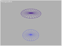
-
Press the "TEXPLODE SELECTION" button - TexPlode will
create two Meshes - one for the Top and one for the Bottom Capping:
-
Press the "Set Selection" again - you will go to EditMesh
Face editing again.
-
From the MAX's Menu, select "Edit/Select Invert" - the
side faces of the Cylinder become selected, the Top and Bottom deselected.
-
Go back to TexPlode
-
Check the [Combine Selections] button.
-
(Optional - you can also check the [Delete Old Mesh]
button)
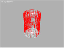
-
Press the "TEXPLODE SELECTION" button again - a third
mesh will be generated from all side faces of the Cylinder.
-
Apply a Cylindrical UVW Map to the third part for later
RadioMapper usage.
NOTE: Both "Delete Old Mesh"
and the actual "TEXPLODE" operations can be Undone separately!
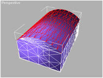
3.2.4.
TexPloding Meshes with Partially Curved Segments
-
You can use the same techniques described above.
-
Use Planar Mapping Coodinates as automatically assigned
by RadioMapper to the Curved Segment, or to multiple segments.
-
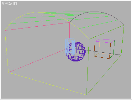
In the case of the Test scene, the floor and the 4 walls
should be texploded to planar meshes, and the curved ceiling to a single
curved mesh.
-
Select the mesh in TexPlode
-
Press [Set Selection]
-
In the EditMesh / Face mode, enter 15,0 into the "Planar
Thresh." field
-
Click on the ceiling - it should become selected:
-
Go back to TexPlode
-
Check the [Combine Selections] checkbutton
-
Press the "TEXPLODE SELECTION" button
-
A single Curved Ceiling mesh will be created:
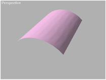
-
Press [Set Selection] again.
-
From the MAX's Menu, select "Edit/Select Invert" - the
side Walls become selected, the Curved Ceiling deselected.
-
Go back to TexPlode
-
UNCHECK [Combine Selections]
-
Press the "TEXPLODE SELECTION" button
-
5 planar meshes will be created:
-
The whole mesh can be processed using RadioMapper now.
3.3.
USING RADIOMAPPER
3.3.1. RadioMapper
Overview
-
The [Pick SOURCE Node]
button is used to select the source Node. You can pick the object with
the mouse, or hit the H key to select from a list.
-
After picking a node, its name is displayed on the button.
-
The [Pick TARGET Node] button lets you set a
completely different object as mapping target. This means that you can
take a copy of the original object before radiosity, or a completely new
object, and apply the radiosity map to it instead to the source radiosity
mesh.
-
The "Set Source as Target" checkbox is activated
by default. The SOURCE object will be automatically set as a TARGET, too.
-
The "BatchMap Selection" checkbutton lets you map all
selected objects at once without picking them one by one.
-
The [RENDER MAP!]
button becomes active after selecting a SOURCE and TARGET nodes. It starts
the mapping process.
-
The "RadioMapper Info" window shows details on the selected
nodes.
-
The "Map and Material Settings" group lets you configure
the output bitmaps.
-
The W and H fields let you enter any bitmap size.
INFO: Since the RadioMapper
rendering is based on the UVW mappings applied, and the resulting bitmap
is assigned using the same coordinates, ANY bitmap size will correctly
fit the TARGET mesh, but you can also enter values that better represent
the mesh proportions. In future releases, the utility will be improved
to set the best bitmap size automatically.
-
The buttons labeled [64][128][256][512] let you quickly
set quadratic 2^n resolutions.
INFO: RadioMapper has
been originally developed and is used for an inhouse 3D Game project with
OpenGL support. Bitmap sizes based on 2^n are required by the OpenGL API.
-
The [Get Path] button lets you select the path
the rendered bitmaps will be saved to.
-
The [Save Config.] button lets you save an INI
file containing the path, bitmap size, file format, and material settings
described bellow. The INI file is loaded on RadioMapper start and used
as defaults next time you launch the utility.
-
The text field bellow shows the saving path. You can
also enter or edit it by hand.
-
The "Prefix" field shows the bitmap name prefix
based on the name of the mesh's name. You cannot edit this field.
-
The [Save Map] checkbutton is checked by default.
You can uncheck it if you want to test-render without generating a file.
-
BUGFIX IN VERSION 1.2:
If you disable map saving, the [Assign Material] checkbutton will be disabled,
and no attempt to assign a material will be made even if [Assign Material]
button is checked.
-
The drop-down list shows the file type to be saved.
Any settings are taken from the MAX's save bitmap "Setup..." settings.
-
The [Assign Material] button lets RadioMapper
create a new material and assign it to the TARGET node. Uncheck it if you
want to keep the exisitng material. The new material uses the rendered
bitmap as Diffuse Map, and has also the following settings:
-
Diffuse Color - some programs use both the diffuse color
and the Bitmap. In MAX, if the Diffuse Map % is bellow 100%, both the Bitmap
and the Diffuse color are used.
-
The "Diffuse Map %" value defines how many percent
of the rendered bitmap to be used in the TARGET material.
-
The Self-Illumination is set to 100% by default, since
Radiosity-mapped objects are already lit and do not need scene lighting.
-
The "UVW Map Options" control the way RadioMapper
reacts when a selected object does not have mapping coordinates.
-
The [Preview UVW Settings]
checkbutton is unchecked by default. When RadioMapper detects a SOURCE
node without texture coordinates, it always adds a UVWmap modifier automatically.
If the [Preview UVW Settings] button is checked, RadioMapper will also
switch to the Modify tab to let you check and modify the gizmo position.
-
The [Zoom on Preview] button
will work only when the [Preview UVW Settings] button is checked. In this
case, RadioMapper will also select the SOURCE node, switch to Perspective
mode and use Zoom Extents Selected to display only the SOURCE node in the
viewport.
-
The "Rendering and Preview" group contains the rendering
settings.
-
The Drop-down list lets you select the desired rendering
method :
-
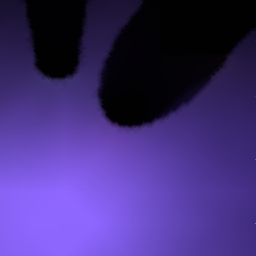
Face Shading uses Gouraud shading and is the
default mode.
-
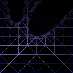
The Edge Shading only connects the color vertices
with colored edges on a black background.
-
The Vertex Shading renders only the color vertices
on a black background.
-
The [Color] and [Mono] buttons work as
radio buttons and let you render a color or greyscale images.
-
The [Optimize Target] checkbutton is checked
by default. After assigning the radiosity map to the TARGET, RadioMapper
applies an Optimize modifier to it automatically - if the TARGET was identical
with the SOURCE, the complex radiosity solution is turned into its original
state before radiosity.
INFO: Before rendering,
RadioMapper removes ANY Optimize modifiers from the Modifier stack of the
SOURCE node. After rendering, in case the SOURCE node is also used as TARGET,
an Optimize modifier is applied again.
-
NEW IN VERSION 1.2: The
[Correct Pixel] checkbutton is checked by default. It corrects single
black pixel artifacts at the left and right edges of the bitmap. You should
uncheck it in case the shaded space isn't rectangular and you want to keep
the black regions outside of the shaded space. The correction function
uses the pixel that is on top of the wrong pixel, which means that
only a single black pixel in the top left or right corner cannot be corrected.
-
The [Spherical Map Shading] checkbutton is unchecked
by default. You SHOULD check it when rendering maps for Spherical objects
with Spherical UVWmap modifiers. This forces RadioMapper to perform special
calculations at the left and right bitmap edges and assure seamless mapping
where both edges meet.
-
The [Close Preview Window] checkbutton is checked
by default and lets RadioMapper close the VFB after rendering a bitmap.
-
The [Verbose Output] checkbutton is checked by
default and enables RadioMapper to report any important events in the MAXScript
Listener.
-
NEW IN VERSION 1.2 : The
[Dynamic Display] checkbutton is now checked by default and is customizable.
The value to the right is set to 10 by default and lets RadioMapper update
the VFB after every 10% progress. You can change the value up to 50, which
will update just once at the middle of the rendering process. Setting it
to 0 works like in older versions. Unchecking the button does not update
the Preview at all except when ready.
3.3.2.
Starting the RadioMapper Utility
3.3.3.
Setting Bitmap and Material Properties
-
The main purpose of RadioMapper is creating Bitmaps
based on the Radiosity solution.
-
Use the two value fields to set the desired Width and
Height for the new bitmap.
-
You can enter any value there, because the resulting
Bitmap is scalled to fit the UVW map and thus will always fit the source
geometry.
-
You can check the mesh size values displayed by the
RadioMapper Info window and enter corresponding values.
-
Since RadioMapper has been originally developed for
use with OpenGL hardware accelerators, there are some OpenGL-specific presets.
-
By pressing the corresponding buttons, you can quickly
set quadratic resolutions like 64x64, 128x128 etc.
-
You should make sure a correct path was set to avoid
any error messages.
-
Click the [Get Path] button - a directory picker dialog
will be displayed.
-
Select the directory where you want your bitmaps to
be saved.
-
The selected path will be displayed in the text field.
-
You can optionally enter a valid path by hand in the
text field.
-
Press the [Save Config.] button to make the currently
set path default. It will be used everytime you start RadioMapper in the
future.
-
Along with the path, the last used bitmap size and format
settings will be saved as defaults.
INFO: The RADMAP.INI file
is written to the root directory of your C: drive. In case the file has
been deleted or corrupted, just press the [Save Path] button again to update
it. This is also the case when you start RadioMapper for the first time.
This might be also required after future RadioMapper version updates.
-
The [Save Map] button should be checked to get
a Bitmap file saved. If you uncheck the button, you will be able to preview
the results of the RadioMapper rendering without overwriting existing files.
-
The drop-down list with file extensions specifies what
file output to be used. Any format settings are taken from the default
MAX settings. To cange them, you should press the Render Scene icon, and
press the "Files..." button. In the save file dialog, select the respective
file extension, and press the "Settings..." button to adjust the settings.
You should use the JPG format for Web-based VRML projects, or the TGA,
PNG and TIFF formats for any other purposes.
-
The [Assign Material] button is checked by default
and causes RadioMapper to create a new material using the rendered RadioMapper
Bitmap in the Diffuse map slot and the color and percentage settings provided
by RadioMapper. In case you have already created a very complex material
hierarchy with an old copy of the RadioMapper Bitmap and want to just rerender
the Map without affecting the material itself, you should disable the [Assign
Material] button. After rerendering the Map, you should also go to the
Material Editor and press the Reload button in the Bitmap slot to get the
latest version of the map displayed.
-
Use the color swatch to define the Diffuse color
for the newly created material. Some programs mix the diffuse map with
the diffuse color. MAX itself mixes them only when the Diffuse Percentage
is lower than 100%. The color is saved to the INI file when the [Save Config.]
button is being pressed.
-
Use the "Diffuse Map %" value to define how many
percents of the RadioMapper bitmap to be used when mixed with the Diffuse
color. This value is written to the INI file.
-
The "Self-Illumination" value corresponds to
the Self-Illum. value in the Material. A material with RadioMapper Radiosity
map is already lit and may not be affected by scene lights. This value
is saved to the INI file.
3.3.4.
Setting UVW Coordinates
A very important step in preparing the geometry for
RadioMapper rendering is providing correct mapping coordinates.
These are required for both Source and Target node
(if different).
-
Pick a Mesh to render - RadioMapper
will check for existing mapping coordinates automatically when you select
a new mesh.
-
It will apply a planar UVW Map modifier to the mesh,
aligning it to the two largest dimensions of the bounding box.
WARNING: If a complex
mesh like the room walls has been processed using TexPlode in automatic
mode, in some cases the two largest dimensions might NOT represent the
plane perpendicular to the normal vector. In this case, the UVW Map modifier
might be aligned incorrectly. This is why it is important to check the
UVW coordinates.
-
RadioMapper will also issue a warning text in the Info
window that you have to check the correctness of the assigned mapping.
-
Check the [Preview UVW Settings]
button before picking the Mesh if you want to control and edit the UVW
Map modifier. RadioMapper will bring you into Modify mode when you select
the Mesh.
-
Check the [Zoom on Preview UVW]
button if you want to have the selected mesh zoomed to the viewport.
-
In the UVW Map modifier, use the Normal Aling and Fit
buttons to correct the planar gizmo alignment and size.
-
If the Target node is NOT the Source mesh, you should
provide UVW mappings by copying the UVW Map modifier from the Source, or
by assigning a new UVW Map modifier.
-
If the mesh is a cylinder, sphere, or any other similar
mesh that can use Cylindrical or Spherical UVW coordinates, you should
set the UVW Map modifier manually before picking the Mesh in RadioMapper
- the exisiting mapping coordinates will be respected and no changes will
be made.
When using the BatchMap mode discussed
later, there will be UVW Map warnings for all meshes in the selection
without mapping coordinates. You should make sure all added modifiers are
aligned correctly before starting BatchMap rendering, or provide the mapping
yourself.
NEW IN RadioMapper
1.2: In V 1.1, in some cases, the shading algorythm leaves single black
pixels at the left or right edge of the texture. This has been fixed in
Version 1.2 - when Verbose Output is selected, a message "Pixel [x,y] Corrected."
will be displayed, where x and y are the pixel coordinates.
3.3.5.
Creating RadioMapper Bitmaps
If you have set your bitmap settings, picked
Source (and optionally a Target), you are ready to render now.
-
The [RENDER
MAP!] button starts the rendering process.
-
A Virtual Frame Buffer will open to preview
the rendering process. To keep it open after rendering, you should uncheck
the [Close Preview Window] checkbox.
-
If you are rendering in Face Shading or Edge
Shading mode, an edge shading image will be calculated first.
-
After that, in case of Face Shading, a second
pass will shade the image completely.
-
The RadioMapper Info window will display the
rendering time in its last line.
-
If the [Verbose Output] button is active,
the following will be displayed in the MAXScript Listener:
RadioMapper Rendering
VIFS04
Rendering Time for
VIFS04: 22222 ms
Saved Bitmap L:\agd\reactor\VIFS04.tga
Material VIFS04
created.
Node VIFS04 Optimized.
End of Rendering.
=================
-
An Optimize modifier is added to the source
mesh if the [Optimize Target] checkbutton is active. This assures that
a Source Mesh used also as Target Node will have only few polygons.
-
If you press the [RENDER MAP!] button again
to re-render, any Optimize modifiers will be removed from the Modifier
Stack first.
-
If you are using
MAX R2, the rendered map will be assigned to the Target Mesh, but because
of a MAXScript/SDK bug in R2 it will not be displayed in the viewports.
You should press the "Show Map in Viewports" manually.
-
If you rerender a map after changing mapping
coordinates, the new bitmap will look different to the older one, but it
will not be updated in the viewports. You should go to the Map slot of
the material in the Material Editor and press the [Reload] button to display
the new state.
-
If the Source and Target Node use Spherical
Mapping coordinates, you should make sure the [Spherical Map Shading]
checkbutton is active before rendering the map. Checking it forces RadioMapper
to do additional calculations to assure seamless spherical textures:
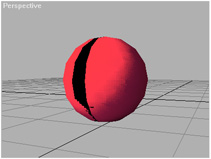
-
In this example, the seam is on the bright
side of the sphere. It is a good idea to have the seam on the shadow side
- you can go to Modify / UVW Map modifier/Sub-Object/Gizmo and rotate it
about Z to change seam position.
-
In the following screenshot, the Bitmap was
rendered with [Spherical Map Shading] turned ON.
![Sphere Mesh Mapped Seamlessly with [Spherical Mapping Shading] ON](tut-sph-seamless.jpg)
-
It is a good idea to keep the [Dynamic
Display] checkbutton at its default state. 10% gives you 10 updates
per map without slowing the rendering much. Lower values will slow down
the process without giving you much more visual information.
-
You can cancel rendering by pressing the [Cancel]
button in the progress bar.
3.3.6.
Using the BatchMap Mode
In case you have split your mesh to multiple
single planes that would render correctly in RadioMapper without any user
input, you can let RadioMapper do the whole work alone. The BatchMap mode
takes any number of Source Meshes from a selection set and processes them
automatically.
-
Press the [BatchMap Selection] button.
-
RadioMapper will check for selected meshes
in the scene.
-
If there are no selected nodes, a message
will appear in the RadioMapper Info window "No Node
Selected."
-
RadioMapper will check all selected nodes
to assure they are all valid Radiosity Meshes. It is a good idea to set
the selection filter to Geometry before selecting meshes for BatchMap processing.
If there are invalid types found (like Cameras, Helpers etc.), RadioMapper
will display an Error Message:

-
The resulting scene uses maps for all mesh
nodes, and has only 372 faces (compare to 9215 in the original radiosity
VRML file)
-
The scene still has the radiosity CPV information,
but it is equal to the original MAX scene.before RadioRay processing.
-
You can select single parts of the scene again
and re-map again with different bitmap settings. You should always go to
Material Editor and click the [Reload] button of the Texture map Bitmap
to see the changes in the viewports.
RadioMapper Version 1.2 Help File
compiled on 9/30/98
DOWNLOAD RadioMapper Convertible Demo