ScriptSpot

Forum topic · Scripts Wanted

DNA WALKABOUT

By tommym · 2011-09-10

Description

Hi GUYS,

I need some brains to work on this script
for DNA Wandering stuff.
I have made 4 straight splines but can go no further.
Now I am trying to attach them and my line keep
rejecting.
If you check my video you see that I am starting
to build the outline of the cube.
It is oriented as shown.

( http://www.youtube.com/watch?v=zhY9RMPmqEo )

I have attached the script that make the 4 lines

--For my Script PAULS DNA WALKABOUT

select $Shape01
max modify mode
subobjectLevel = 0
modPanel.setCurrentObject $Shape01.baseObject
splineOps.startAttach $Shape01

_____need to attach $Shape02 $Shape03 $Shape04

THANKS from
Paul

Attachments
Comments (24)

DNA walkabout

tommym · 2011-09-29

Anubis

Have you given up on DNA walkabout ?
I have no reply

Paul

?...

Anubis · 2011-09-29

What you mean?
I remeber I done and close my assistance on this one :)

sorry for the delay

Anubis · 2011-09-17

I think we can move this to email response.
I follow your instruction and looks like the scene is ready, but I can send the .max file to confirm.
Just mail me to: anubiss(at)abv.bg

Uh :)

Anubis · 2011-09-15

As I work and try to help at the same time, I presume will miss something :) I move the pivot pos to [0,0,0] on Vertical, but forgot about rotation. At the moment I can only promise to repeat the test as soon as I can ;)

DNA walkabout

tommym · 2011-09-15

OK Anubis

I think I have solved the problem. We have lost all pivots.
I am enclosing a new OBJ set, It is oriented different so what you have
to do is make the VERTICAL parent and LINK every thing and repostion the VERTICAL to 0,0,0 rotate 90,0,0
except a new cube outline and box in 000 these can be used to replace the others by reorientating
135, -35.264, 30 this will bring everything back to MAX.

Paul

Attachments

DNA walkabout

tommym · 2011-09-15

Hi Anubis

It is essential that you use front view. If the vertical axis is not showing the correct orientation and pivot rotation the copy will do things wrong. Also I usually use a total dummy for everything and zero to world axis. But I could not with OBJ files.

Paul

DNA walkabout

tommym · 2011-09-14

I just checked again in front view World axis.

Vertical Pos 0,0,0 rotation 90,0,0

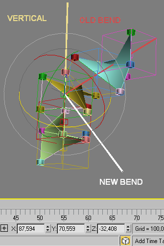
New axis Pos 0,0,0 rotation 87.595,70.559 ,-32.408 absolute world

Are you in front view ?

DNA walkabout

tommym · 2011-09-14

Did you see my last it should be minus -32.408 I forgot the minus sign

test

Anubis · 2011-09-14

here is whats happens with new bended axis (white color):

Attachments

DNA walkabout

tommym · 2011-09-14

I just checked and the Z 32.408 should be -32.408

DNA walkabout

tommym · 2011-09-14

that did not work here is another

Attachments

Anubis · 2011-09-14

Ok, will review it later ...

DNA walkabout

tommym · 2011-09-14

OK Anubis

I have made up a PNG for you also.

Paul

Attachments

puzzle out

Anubis · 2011-09-14

Hi Paul,

I import the .obj file successfully and made a screenshot to can see what i've got. All base and offset transform of all objects are fully reseted. Also read your last post 3-4 times and get lost :)

Attachments

DNA walkabout

tommym · 2011-09-13

OK Anubis.
I have enclosed the folder DNA OBJ Files no mats allowed. They are all named
and they come in OK. The colors are different but you will have to go into properties
and alter back face nul. The diags & boxes have been added so you can
check for spot on. But they could also be used to look real sharp as rungs
they will bring home the perfect geometry of the DEE & SPAGO

In the cube outlines I have encluded a purple vert AXIS and a yellow bend AXIS
The orientation rotate will be lost in the OBJ files.
So in world axis the purple pivot is pos 0,0,0. rotation 90,0,0
You will have to copy and give the copy a rotation of 87.594 , 70.559 , -32.408

This will be the bend axis sys coords. I have repositioned a green DEE to this axis
This DEE at 180 rotation to the vertical dee set.
When you nudge up a cube copy the distance is 692.815 and is the same for the cubes
to nudge in the Z along the bend axis.

when you nudge up A copy of a DEE you use 692.815 plus 120 rotate in Z axis
It is the same proceedure on the bend axis. But you can rotate the cube outline 120
also but it is optional. So like in the video the SPAGO must rotate with 0-1-2.

I mentioned the 35.264 not being perfectly spot on and I found this on the web
35.26438698 it comes from tetrahedron geometry.

Hope you can read the files

Paul

Attachments

OK

Anubis · 2011-09-13

As you feel I can help then there nothing to worry about ;)
Btw, many abstract mathematical theories available out there (chaos theory, catastrophe theory, numeric theory), they all are hard for absorb but very interesting anyway, while practical maths are so boring to me :)

DNA walkabout

tommym · 2011-09-13

Hi Anubis.
I will attach OBJ files tomorrow they can be open with a text editor also for
coordinates. There is no sweat about math it is just the 35.264 angle maybe varies 265 264
(it is a tetrahedron angle) it is just that when you look at the vertex positions they vary very slightly. I made the Dee and Spago from a 6 point edit poly plane. It does the job and you can create them the same with your previous script I was concerned about the nurb swirls
eating up the bytes. But the the 6 points looking like perfect geometry. Please do not sweat on this. You will soon get familiar with the geometry slow but sure, (Rome was not built in a day). It is a thousand times simpler than that there chaos theory I did not go to university.

Paul

Hi Tommy

Anubis · 2011-09-13

The maths (especially algebra and geometry) is not my strong side :( I was curious though, and only reading your post do not helps me to catch what you're after, so I try to open the scene file but w/o success (see the screenshot). Since I saw before the second plugin in the list of missing dll's, I think that you save that scene in a higher Max than main (2009). Ok, never mind, if you have scripting question and I can help... at least will try ;)

Attachments

DNA walkabout

tommym · 2011-09-12

OK Anubis
I am enclosing the geometry for the DEE and SPAGO setup
If anybody wants play around you are quite welcome.
But not commercially. The cubes are oriented at 135, -36.264, 30
but it does not seam to balance spot on. If I play with the 264 it makes things worse. Maybe somebody can figure this out. I show the axis at
a sys coord of 70.206,-9.805,-123.353 seams pretty good. But it would be nice if somebody up in maths could verify these angles. I have kept the DEE and SPAGO down to 6 vertices. So it should dance about with min memory.
So it is down to script experts now.
From Paul

Attachments

DNA walkabout

tommym · 2011-09-12

Anubis
I am working on a new DEE and SPAGO I will let you have them 6 vertexes apiece
for min memory.
Paul

DNA WALKABOUT

tommym · 2011-09-12

It can support the pair of us 50 50

thanks

Anubis · 2011-09-11

Glad to know I have support the science with something :)

DNA Walkabout

tommym · 2011-09-10

Wow thanks Anubis,

You make it look so easy. The next step is to turn this into the cube outline
The outer cube edges are 700 by 700 by 700 and the center inner cube is 100 by 100 by 100
What I aim to end up with is to get the DNA "DEE" and "SPAGO" to string along like crazy by just punching in the numbers 0.1.2 with S or feeding a text and produce a DNA 4 Color String to move to perfect order around in 3d space. Which could be a big thing for science. I realize this is putting you guys out a bit
but it will not see daylight without your help.
Thanks from Paul

interesting video...

Anubis · 2011-09-10

First to say, forget all

splineOps

functions as soon as possible. They are kernel of bugs that corrupt the scene. The rest functions for shapes are fine, but splineOps is a full garbage.

So, you need to draw the lines one by one and then attach them? If so, you can use

addAndWeld

(but below will show an alternative):

fn drawLineBetweenTwoPoints pointA pointB =
(
	ss = SplineShape pos:pointA
	addNewSpline ss
	addKnot ss 1 #corner #line PointA
	addKnot ss 1 #corner #line PointB
	updateShape ss
	ss
)

-- draw lines...
sp1 = drawLineBetweenTwoPoints  [0,0,606.213] [494.976,-285.774,202.087]
sp2 = drawLineBetweenTwoPoints [0,0,606.213] [-494.976,-285.783,202.087]
sp3 = drawLineBetweenTwoPoints [0,-571.557,-202.059] [494.976,-285.783,202.087]
sp4 = drawLineBetweenTwoPoints [-494.963,-285.774,202.067] [0,-571.557,-202.059]

-- as the 4 lines w'd become 1 shape - you can leave this part for the end
-- and just say: (sp1.wirecolor = color 0 252 252)
#(sp1,sp2,sp3,sp4).wirecolor = color 0 252 252 -- set wirevcolor for all

-- addAndWeld...
addAndWeld sp1 sp2 0.1
addAndWeld sp1 sp3 0.1
addAndWeld sp1 sp4 0.1
updateShape sp1

-- so you end with 1 closed shape
isClosed sp1 1 -->> true

As you know the coords, the alternative (more easy) way w'd be to draw entire shape at once (no needs attaching in this case):

-- here is a custom function
fn DrawShape pntCoords wColor = (
	ss = SplineShape pos:pntCoords[1]
	addNewSpline ss
	for i = 1 to pntCoords.count do (
		addKnot ss 1 #corner #line pntCoords[i]
	)
	close ss 1; ss.wirecolor = wColor
	updateShape ss; ss
)
-- define array of Point3
arrPoints = #(
	[0,0,606.213], [494.976,-285.774,202.087],
	[0,-571.557,-202.059], [-494.963,-285.774,202.067]
)
-- call the function
newShape = DrawShape arrPoints (color 0 252 252)

Cheers!