CONTENTS:
In this fourth step, we are going to add mesh generation
capabilities to the utility.
We are going to include mesh generation and color-per-vertex
assignment.
The complete script source can be found under
http://www.scriptspot.com/bobo/mxs2/mxs_tut/lesson04.zip
Download the ZIP file and copy its content into the
same directory as in LESSON 01.
utility lesson04
"Lesson04"
(
group "About..."
(
label lesson_label01
"Lesson 04 Script"
label lesson_label02
"by Borislav Petrov"
label lesson_label03
"Kinetix Forum Assistant"
)
group "Settings:"
(
radiobuttons
geom_mode "Geometry" labels:#("Box","Sphere","Color-Per-Vertex Mesh") align:#left
An additional label
for the Mesh creation has been added to the radio buttons.
Note that MAXScript
will automatically reorder the radio button entries vertically to fit the
rollout.
dropdownlist effect_mode
"Effect Source" items:#("Luminosity","Red Channel","Green Channel","Blue
Channel","Alpha Channel")
spinner sphere_segs
"Sphere Segments:" range:[4,16,4] fieldwidth:40 align:#right type:#integer
enabled:false
spinner base_size
"Base Size:" range:[1,1000,100] fieldwidth:40 align:#right
spinner multiplier
"Effect Multiplier:" range:[0.1,10,2] fieldwidth:40 align:#right
spinner nth_pixel
"Every Nth Pixel:" range:[1,10,1] fieldwidth:40 align:#right type:#integer
button get_image
"Get Image File" width:140
edittext bmp_name
"File" text:"c:\\mxstut\\m.tga"
label size_label
"Image Size:???x???"
)
group "Action"
(
button start_process
"LET'S DO IT!" width:140 height:30 align:#center enabled:false
button remove_all
"Clean up scene" width:140 align:#center
)
fn Check_bmp_size
bmp_n =
(
try
(
bmp_check
= openbitmap bmp_n
bmp_w =
bmp_check.width
bmp_h =
bmp_check.height
close bmp_check
size_label.text
= "Image Size:" + bmp_w as string + "x" + bmp_h as string
)
catch
(
start_process.enabled
= false
)
)
on geom_mode changed
state do
(
if state == 2
then sphere_segs.enabled = true else sphere_segs.enabled = false
This line changed
a bit - it has been inversed.
It checks for state
== 2 now, and enables the Sphere segments only when the Sphere option is
selected.
In the older versions,
there were just two possible states and checking for state == 1 was ok.
)
on bmp_name entered
txt do
(
file_check
= getFiles bmp_name.text
if file_check.count
== 1 then
(
start_process.enabled
= true
Check_bmp_size
bmp_name.text
)
else
(
size_label.text
= "Image Size:???x???"
start_process.enabled
= false
)
)
on get_image pressed
do
(
pick_image =
selectBitmap caption:"Get Image File"
if pick_image
!= undefined then
(
bmp_name.text
= pick_image.filename
start_process.enabled
= true
Check_bmp_size
bmp_name.text
)
)
on start_process
pressed do
(
work_bmp = openbitmap
bmp_name.text
bmp_w = work_bmp.width
bmp_h = work_bmp.height
progressstart "Generating Objects..."
mesh_verts = #()
mesh_cpv = #()
These to new ARRAYS
are initialized and will be used for mesh creation.
The first one will
hold the 3D coordinates of the vertices.
The second one will
hold the vertex colors.
for h = 1 to bmp_h
by nth_pixel.value do
(
pixel_line
= getpixels work_bmp [0,(h-1)] bmp_w
if not
progressupdate (h as float /bmp_h *100) then exit
for w =
1 to bmp_w by nth_pixel.value do
(
case effect_mode.selection
of
(
1: size_value
= base_size.value + multiplier.value*(pixel_line[w].r+pixel_line[w].g+pixel_line[w].b)/3
2: size_value
= base_size.value + multiplier.value*(pixel_line[w].r)
3: size_value
= base_size.value + multiplier.value*(pixel_line[w].g)
4: size_value
= base_size.value + multiplier.value*(pixel_line[w].b)
5: size_value
= base_size.value + multiplier.value*(pixel_line[w].alpha)
)
case geom_mode.state
of
(
1: new_object
= box length:base_size.value width:base_size.value height:size_value
2: new_object
= sphere radius:(size_value/2) segs:sphere_segs.value
3: (
append mesh_verts [w*base_size.value, (-h*base_size.value), size_value]
append mesh_cpv pixel_line[w]
)
These new lines
add the new options needed to gather vertex and color information for the
mesh to be created.
The append
command adds a new entry to the end of an existing array.
This way, we collect
the coordinates and colors for each vertex which will correspond to a single
pixel.
)
if geom_mode.state
!= 3 then
(
The following lines
remain as they were, but they will be executed only when NOT creating a
mesh.
new_object.pos
= [w*base_size.value, (-h*base_size.value), 0]
new_object.name
= uniquename "4th_Lesson"
new_material
= standardmaterial diffuse:pixel_line[w]
new_material.name
= new_object.name
new_object.material
= new_material
)
)--end w loop
)--end h loop
if geom_mode.state
== 3 then
(
Here starts the new code for Mesh creation.
new_object
= mesh length:(bmp_h*base_size.value) width:(bmp_w*base_size.value) lengthsegs:(bmp_h/nth_pixel.value-1)
widthsegs:(bmp_w/nth_pixel.value-1)
The above line creates
a new mesh object which is a grid with the respective size and number of
segments.
Because we are going
to have vertex-to-pixel correspondence, we need the number of segments
to be the number of pixels minus one!
NOTE that
there are three different ways to build a mesh in MAXScript - the above
one creates a grid. The other two let you create a mesh based on arrays
of vertices and faces, and to create a mesh with just the number of vertices
and faces set, and set the data for each vertex and face separately.
For more, check
the MAXScript Online Help.
setnumcpvverts
new_object mesh_cpv.count
We have to decalre
the number of Color-Per-Vertex vertices (the elements that hold vertex
color information in the second UVW channel)
We use the number
of the collected color values from the array.
for i =
1 to mesh_verts.count do
(
Now we start looping
through all vertices in the mesh.
setvert
new_object i mesh_verts[i]
The setvert
command sets the 3D coordinates of a vertex.
You have to supply
the object, the index number of the vertex to set, and a Point3 value [X,Y,Z]
NOTE that
after making any changes to a mesh, you have to execute the update
() command to see the result in the viewports.
setvertcolor
new_object i mesh_cpv[i]
This command sets
the color of the indexed vertex of the object to the supplied color [R,G,B].
)
normal_mod
= normalModifier flip:true
We create a new
modifier.
Modifiers are also
MAX objects and are created the same way as geometry, materials etc.
We have created
a new Normal modifier to flip face normals.
addmodifier
new_object normal_mod
The addmodifier
command adds a modifier to the object.
By default (as in
our case), it is added on top of the modifier stack.
We need this modifier,
because the original grid had its vertex 1 at coordinates [0,0,0] and the
last at positive direction.
Because the bitmap
goes from [0,0] down in the negative Y direction, all vertices of the grid
have been moved, and all faces inverted.
We need to flip
the normals to see them.
collapsestack
new_object
The collapsestack
command collapses the modifier stack. (What surprise! :o)
We get an EditableMesh
object without the modifier on the stack, but with its effect reflected
by the mesh...
defaultVCfaces
new_object
VertexColor information
requires not only color vertices, but also color faces.
When the vertex
information is already present, MAXScript can build the required faces
automatically based on the mesh topology.
update new_object
As already mentioned,
we need to update the mesh to see all sub-object level changes made so
far.
new_object.name
= uniquename "4th_Lesson"
Set a unique name
as usual...
vert_color
= Vertex_Color ()
We create a new
Map to use in a material.
The Vertex_Color
() map is used to show VertexColor data in the production renderer.
new_material
= standardmaterial diffusemap:vert_color
We create a standard
material as usual, but instead of a diffuse color, we assign the already
created Map to the diffuse map channel.
new_material.name
= new_object.name
new_object.material
= new_material
Same as usual...
new_object.showvertexcolors
= true
We have to set the property of the EditableMesh
to show the VertexColor in the viewports.
This property corresponds to the Display
Tab/Vertex Color checkbox.
)
progressend ()
max views redraw
close work_bmp
)--end on button
pressed
on remove_all
pressed do
(
q_answer = queryBox
"You are about to delete all objects\ncreated by the Utility.\nAre you
sure?"
if q_answer then
(
delete_array
= $4th_Lesson* as array
delete
delete_array
)
)
on lesson04 open
do
(
file_check
= getFiles bmp_name.text
print file_check.count
if file_check.count
== 1 then
(
start_process.enabled
= true
Check_bmp_size
bmp_name.text
)
else
(
messagebox
"The Image file couldn't be found!\nPlease select a valid one."
)
)
)--end utility
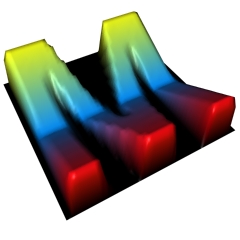
Here is what happens when you execute the
script with
Mesh, Red Channel, Base 100, Scale 4.0,
Nth 1
Have fun!
Borislav Petrov [FA]